
Sample tutorial in this site
Author: 3dknot
I hope to cover all the basic steps of creating ceramic pot such as modeling, UVW mapping, texturing, lighting and rendering from this tutorial. However this is not a step by step tutorial and I hope you are having the basic knowledge on 3d max as well as on Photoshop (for creating textures).Go to front viewport and draw the one half of the cross-section of the pot you want to model using a line. No need to make it smooth or add more details, you can add them later.

Go to modify list and add Lathe modifier. Set the number of segments to a value 8 to 16. However the number of segments you are setting should be dividable by the number of repeating textures around the pot. If it is not clear go through the following examples.
No. of repeating textures No. of Lathe Segments
2 8, 10, 12, 14, 16
3 9, 12, 15
4 8, 12, 16
5 10
6 12
My model will have 3 repeating textures (and 6 in some places), so I have selected 12 segments.

Convert the object to Editable Poly object, go to Vertex sub-object level and select all the vertices and weld them once. Closely look at the mesh to identify whether any unwanted vertices are welded (you need only to weld the vertices at the axis of the lathe.) if any unwanted vertices are welded, undo once, go to top viewport, select the vertices on the centre axis of the pot and weld them. Exit from the sub-object level.
Apply turbo smooth modifier to the pot with 2 Iterations. Definitely what you are seeing on the viewport is not the one you wanted to see. Don’t worry about that. This is the way to correct it.

Go back to sub-object level of Editable Poly object; select one of the edges you want to make sharper. Press Loop button in the Selection rollout to select entire ring of edges and Chamfer the edges a bit (see the figure below) using Chamfer button in the Edit Edges rollout. Repeat it to all the edges you want to make sharper.
Go back to TurboSmooth modifier and see the difference. I hope you got what you wanted. Do the final
adjustments to the model, you will not get a chance to edit it again. (However you may able to further smooth the model later using TurboSmooth modifier.)

Place the center of the object at (0, 0, 0). It is not a must , but it will make future works easier.

Now we know we can get the correct shape of the pot by applying TurboSmooth modifier. Therefore delete the TurboSmooth modifier; we can apply it later at the final stage of this tutorial. Go to Polygon sub-object level and delete 5/6 part of the object, by keeping 1/6 of the object. (That because I am having 3 repeating textures. If you having 4 repeating textures keep 1/8, if 5 keep 1/10. Generally keep 1/(2 x No. repeating textures) and delete the remainings)

Turn no Angle Snap toggle and rotate the remaining part of the object and place parallel to X or Y axis. Apply Unwrap UVW modifier, Press Edit button to open Edit UVWs window. Select all the faces and drag them somewhere outside the boundary and close the window.

Go to Select Face sub-object of the Unwrap UVW modifier and select only the faces where the textures will be. In my case there will be only 8 polygons. Open Edit UVWs window again and apply Flatten Mapping (Mapping > Flatten mapping) for the selection with default settings. You will get a clear unwrapping layout. If you not interested in it, modify it as you like. Finally scale down the remaining mapping faces outside the boundary and place the somewhere inside the boundary but outside the existing faxes. (I have modified all the faces to square faces. See the figure below)

Now mapping part is complete. The proper way of exporting this UVW map to Photoshop is use Rrender To Texture. But in this case UVW mapping us very simple, therefore open Edit UVWs window and zoom the required area and take a screen shot. You can use any size of map (256×256, 512×512, 1024×1024, 2048×2048) I prefer 2048×2048 map. Paste the screenshot and scale the UVW boundary to match with map size. Now you know the areas to place the texture maps. Here I am not going to teach you how to make the texture.

This is the map I have prepared.

To apply the texture, open Material Editor, select one material slot and set the prepared map as Diffuse and Specular colour maps. Add Raytrace map as Reflection map. Increase the Specular level and Glossiness level. Switch on Show Map in Viewport button. Select the remaining part of the pot and press Assign Material to Selection button in the Material Editor to apply the material.


Convert the remaining part of the pot to Editable Poly. Go top viewport and take copies around the main axis to make the pot complete (I am going to add 5 more copies). Attach all the part together, go to Vertex sub-object level and weld vertices at the edges to connect all parts together.

Apply TurboSmooth modifier with 2-3 Iterations.

Render and see.
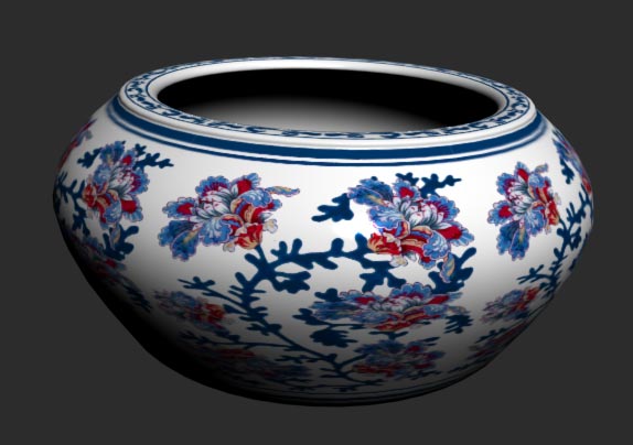
Now it looks good. To make it more realistic, go to top viewport and draw a plane at the bottom of the pot. Prepare a material with dark gray in colour with a Raytrace map as Reflection map and set the amount as 50%. Apply it to plane and render to see the difference.

Now you need to find a HDRI image (you will be able to find an image through internet, if you currently haven’t one). Press <8> to open Environment and Effects dialog. Click the None button (Environment tab > Common Parameters > Background) browse the HDRI (or .hdr) image and press Open. When you press open, HDRI Load Settings dialog will appear. There are some parameters under histogram. You can change them as you want later, just press OK now.

Open Material Editor and drag the Background map from Environment and Effects dialog to empty material slot. Select Instance from the dialog appear and press OK. Now you can change the properties of the map from Material Editor. Go to Coordinates rollout and change the mapping type to Spherical Environment.

If you are not interested in the way how the reflection map looks like, now it’s time to change it. Select the material slot and go to Bitmap Parameters rollout and press the button in front of the Bitmap. (it is already having the map selected as environment map). Go to Setup option in the Select Bitmap Image File, HDRI
Load Settings dialog will appear. There are mainly two values which can be changed, the Black Point and the White Point. The appearance of the bitmap under current settings is displayed on the image on the bottom left side. The areas marked as black will not visualize through the Raytrace when rendering. Same way the areas maked as white will visualize as pure white through Raytrace. Remember to copy the Liner value of White point before press OK. Paste the copied value as RGB Level value under the Output rollout. Render and see the difference. Repeat this until you satisfies.
Now the final part, it is very easy. Place a Skylight anywhere on the plane. Go to Render Scene dialog (press <F10>) > Advanced Lighting tab > Select Advanced Lighting rollout and select Light Tracer. Keep existing settings. Render and see. When you taking the final rendering increase the Rays/Sample to higher value (1000) and Bounces to 2.
Hope you enjoy this tutorial.

No comments:
Post a Comment